
Phone: +86 15398058207
E-mail: sales@astraroll.com
Add: Room 603 Building C, The Huixin Center, Zhangba One Road, Yanta Zone, Xi'an City, Shaanxi Province, China
Different Types of Conveyor Belt Pulleys
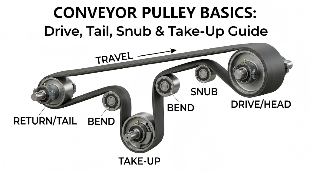
Many procurement non-professionals confuse the two, but they are fundamentally distinct:
Conveyor Rollers: These are passive, supporting components distributed in large numbers across the conveyor bed or return section. Their main purpose is to support the conveyor belt and the material load, minimizing frictional resistance.
Conveyor Pulleys: These are active components used for system control and drive power. Usually located at the ends of the conveyor system (head and tail) or at the take-up assembly, they have a significantly larger diameter than standard rollers and are used to drive the belt, redirect belt travel, or adjust belt tension.
This technical guide breaks down the definitions, working principles, and selection metrics of the essential types of pulleys within a belt conveyor system.
I. Core Types and Functions of Conveyor Pulleys
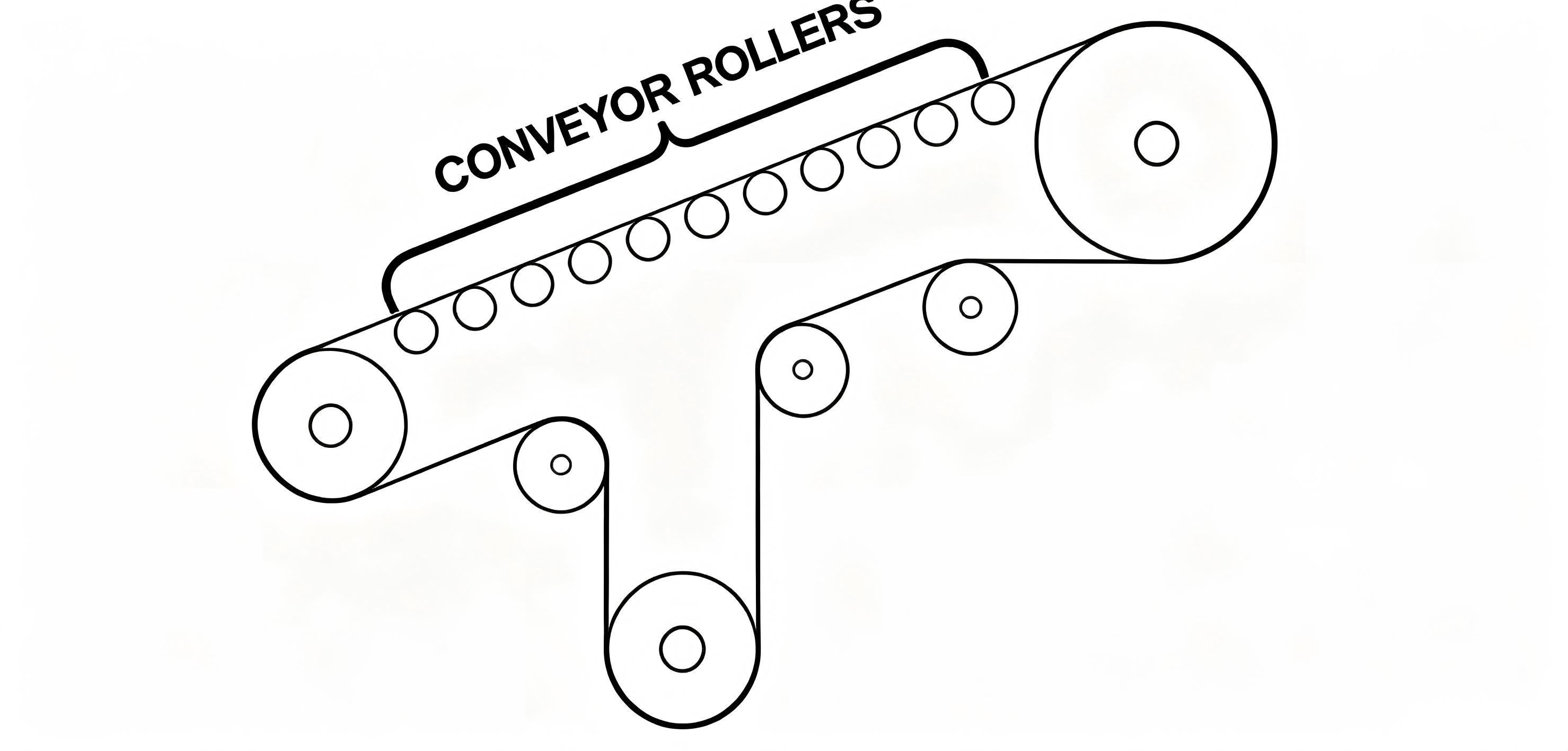
Within a complete belt conveyor system, pulleys in different locations work in tandem to maintain stable belt tracking and tension. Based on global industrial standards, the core classifications include:
1. Drive / Head Pulley
Location & Definition: Typically mounted at the discharge end (head) of the conveyor. It serves as the primary power source of the entire system.
Working Mechanism: An external motor connects to the shaft of the drive pulley via a reducer or coupling, forcing it to rotate. Utilizing the friction on the pulley surface, it drives the entire conveyor belt forward. To increase grip and prevent belt slippage, the surface of a drive pulley is usually modified with a rubber coating (Rubber Lagging).
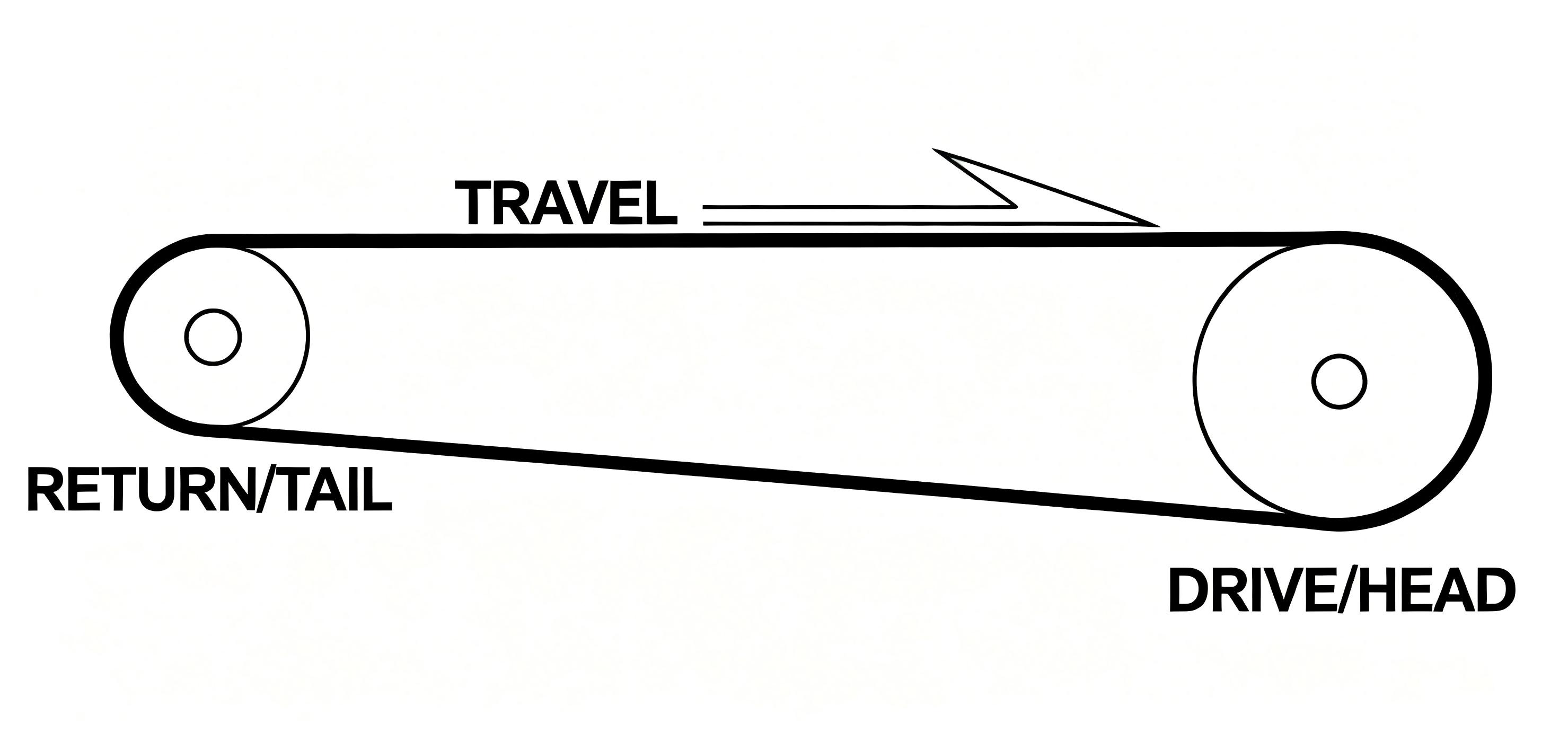
2. Return / Tail Pulley
Location & Definition: Located at the loading or receiving end (tail) of the conveyor system where the belt reverses direction.
Working Mechanism: Its core function is to redirect the incoming conveyor belt back to the drive pulley. On shorter conveyor lines, the tail pulley often pulls double duty as a "take-up pulley," utilizing tail-end adjustment screws to regulate the belt's initial tension. It can be mounted using either internal bearings or external pillow block bearings.
3. Snub Pulley
Location & Definition: Installed immediately adjacent to the drive pulley, typically on the return belt side just below it.
Working Mechanism: Its primary purpose is to increase the belt wrap angle around the drive pulley. A larger wrap angle increases the contact surface area between the belt and the driving wheel, which significantly boosts driving traction and prevents belt slippage under high-load operations.
4. Take-Up Pulley
Location & Definition: Commonly found in long-distance conveyor systems, working in conjunction with gravity (counterweight) or mechanical take-up assemblies.
Working Mechanism: Over long periods of heavy load stretch, conveyor belts inevitably undergo physical slackening. The take-up pulley moves vertically or horizontally to actively absorb the slack, providing continuous, constant tension to ensure the drive pulley does not slip and the belt does not sag between rollers.
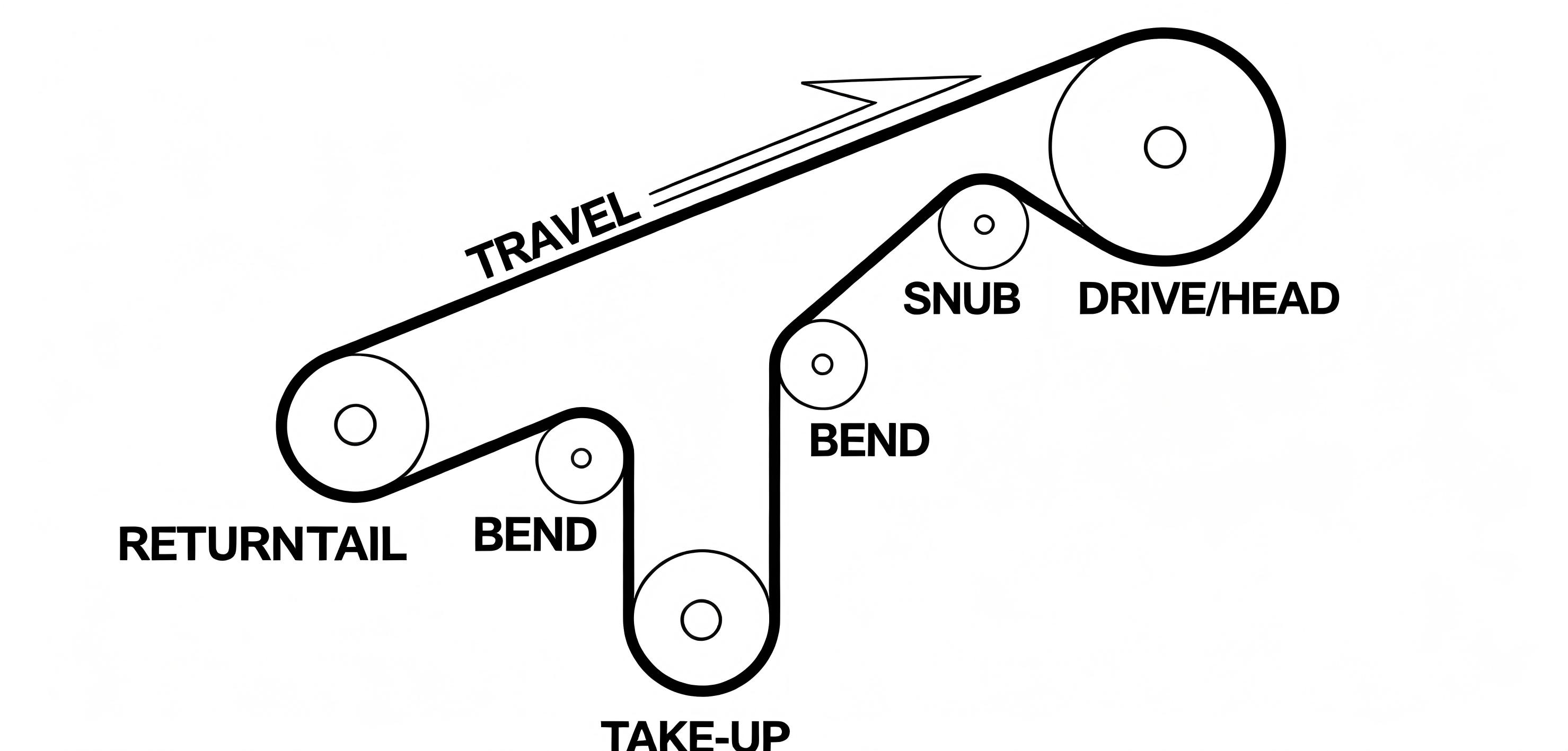
5. Bend Pulley
Location & Definition: Positioned at internal turn points or at the directional changes of a vertical take-up loop.
Working Mechanism: Specifically engineered to change the direction of the belt path. In complex, non-linear, multi-tier routing conveyor networks, bend pulleys are indispensable for guiding and tracking the belt loop along its intended structural path.
6. Idler Pulley
Location & Definition: Any pulley used in a non-drive position that is designed to rotate freely.
Working Mechanism: These carry no independent power source. They rotate purely via the friction generated against the moving conveyor belt, serving to keep the belt traveling along a linear path within specific zones.
II. Roller vs. Pulley Configuration Comparison
To better visualize their distinct placements and structural footprints within an overall material handling setup, refer to the following belt conveyor component sheet:
| Component Name | Typical Quantity Per Line | Core Physical Attributes | Primary Engineering Purpose |
| Conveyor Pulley | Usually 2 to 6 units per system | Large diameter (typically ≥100mm to hundreds of mm), thick shell walls, robust heavy-duty shafting. | Transmits motor torque, changes belt direction, and controls system tensioning. |
| Conveyor Roller | Dozens to hundreds of units per system | Small diameter (e.g., Ø50, Ø60, Ø76mm), installed in dense, linear batches. | Directly supports the weight of the belt and materials, lowering rolling resistance. |
III. Engineering Selection Guide: Sourcing High-Quality Conveyor Pulleys
Because pulleys bear the massive tension forces of the belt and the rotational torque of the motor, they are highly stressed mechanical components. Procurement teams must strictly evaluate the following mechanical parameters:
Cylindrical Accuracy & Dynamic Balance:
Large-scale pulleys running at high operational speeds will cause severe belt vibration, mistracking, or tearing if they exhibit excessive radial run-out. Pulleys must be precision-turned on advanced CNC machinery and undergo rigorous dynamic balancing verification.
Surface Lagging Materials:
Plain / Steel Face: Suitable for non-drive configurations such as tail, bend, or snub pulleys where extra friction is not required.
Rubber Lagging: The gold standard for drive pulleys. It can be grooved with Herringbone or Diamond patterns to shed water and debris in wet, dusty environments, maximizing belt grip.
Shaft-to-Shell Connection Style: Under heavy-duty cyclic loading, traditional fully welded shafts are highly susceptible to fatigue fracture at the stress concentration zones. Heavy applications strongly recommend utilizing a keyless locking assembly (Taper-Lock Bushing), which simplifies non-destructive maintenance and shaft replacement.

IV. Conclusion: Why Partner with AstraRoll for Your Conveyor Systems?
When building high-load, long-distance, or high-precision industrial conveyor lines, the reliability of each pulley directly impacts the overall operational efficiency of your facility. AstraRoll combines cutting-edge material science with precision machining to deliver a comprehensive suite of engineered pulley solutions:
Global Quality Standards: Our drive and tail pulleys are rigorously built to withstand heavy-duty, high-speed automated operations, passing strict shaft non-destructive testing (NDT) and complete dynamic balance tuning.
Full-Stack Bespoke Engineering: Whether you require heavy taper-lock pulleys for specialized mechanical interfaces or corrosion-resistant stainless steel bend pulleys for unique factory environments, we deliver a 1:1 match based on your technical submittals.
Superior Material Versatility: We offer specialized lagging options featuring permanent flame retardancy, extreme wear resistance, and ESD-dissipative properties to systematically eliminate system risks like belt slippage and static charge accumulation.
Looking for high-durability Conveyor Pulleys or need an evaluation of your existing system configuration?
Contact the AstraRoll engineering expert team today to secure a technical consultation and your custom project quotation!
- Explosion proof electric roller
- The Silent Quality Drivers: How High-Precision Rollers Shape Release Film Perfor
- What Are the Benefits of Hard Anodized Aluminum Guide Rollers?
- Why High-End Manufacturing Cares So Much About Roller Surface Precision
- Why Your Heavy-Duty Conveyor Needs Garland Idler Rollers
- What are the differences and applications between anilox roller and embossing ro
- Why Teflon Coated Aluminum Rollers Are the Best Choice for Non-Stick Web Handlin
- How to Eliminate Static Accumulation and Defect Risks in High-Speed Battery Sepa